High Rise Salon Mechanical Plan Drawing Chicago Hydraulic
The reemergence of our core cities as more active and vibrant communities brings pressures and challenges to those who blueprint. The density of buildings, traffic, the scarcity of land, and a competitive spirit among developers are all factors that work together to push modern buildings higher.
Sometimes, especially in motion pictures, we envision high-rise buildings as towering skyscrapers. While this is the romantic and non always wrong vision, a "high" ascension tin can be as brusque as viii to 10 floor levels. The National Fire Protection Association (NFPA) defines a high-rise building as a building with an occupied floor that is 75 feet in a higher place the level where the firefighting apparatus would stage firefighting operations. That low threshold requires several specific features to be designed into buildings to promote life safety and allow for emergency responders to safely and speedily admission the college levels of the building, thereby saving lives and considerable invested resources. With that adequately elementary definition, all high-ascent design challenges should be the same, right? Perhaps some additional discussion is warranted before nosotros make that determination!

Pressure Bug
High-rising design and structure present more than a few special challenges, peculiarly regarding the design of plumbing systems. Some of the biggest challenges to high-rise plumbing design chronicle to controlling pressure. Pressure is both friend and foe in plumbing systems. Plumbing engineers learn early on that as you lift water in a higher place a datum, you lose one pound per square inch for every 2.3 anxiety of top. While this may seem a reasonable incremental loss, it can be a significant penalty when the water is raised 75 feet; then, a requirement is added to maintain a loftier minimum pressure at the top of the cavalcade. Many designers answer this claiming daily.
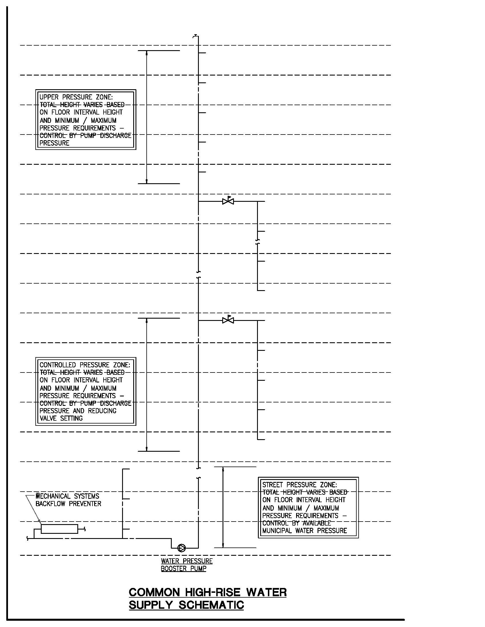
For instance, a common condition in a h2o riser serving a toilet group in an office building supplied with flush valve fixtures requires 25 psi at the most remote fixture. Yous add together a pressure boost arrangement to come across that need on the top floor. A common complication begins when you brainstorm to stack floors. The combined head pressure causes the pressure at the bottom may exceed the commanded rubber level equally express by code and materials. This too is a fairly routine condition that often is solved by either placing pressure level-reducing valves on each level where pressure exceeds code maximum or branching from the higher pressure riser to make a force per unit area zone. This pressure zone uses a cardinal pressure-reducing valve and sub-riser to meet the minimum force per unit area required at the highest level and the maximum force per unit area allowed at the lowest level. This item method has been used successfully in many high-rise edifice designs.
Supplying adequate water pressure at all levels of the building is critical for building occupants, although economics, basic building functions, and overall heights have significant impact on methods of water supply distribution. Numerous intermediate-height and even very tall high-ascent buildings use diverse pumping schemes. One early method used elevated storage tanks at the top of the building with fill up pumps at the lesser of the edifice, a classic gravity downfeed organization. This method evolved into direct pumping systems using multiple pump packages with constant-speed, constant-pressure controls. Both of these methods proved to exist reliable and affordable through the years, and many such designs are still active today or still are used in current blueprint practices. Standing improvements and development of variable-frequency electric drives and an ever-increasing emphasis on reducing energy consumption and costs make the variable-speed, direct-pumped package a modern workhorse of the manufacture.
The critical need to provide acceptable flow and pressure gives the loftier-rise plumbing engineer ample opportunity to practice their craft. A thorough understanding of pumping nuts is disquisitional to showtime with, and ane of the most widely recognized sources is the Fluid Handling Grooming and Instruction Department of ITT Industries, better known equally Bell and Gossett's Little Red School. From this fundamental training, more avant-garde texts could include the Pumps and Pumping Systems Handbook, published by ASPE, as well as training brochures published by all reputable pump manufacturers and organization packagers. Even the seasoned professional can benefit from occasional review of these texts to refresh some of the basics and rediscover some of the subtleties of pressure booster systems.
Drainage
Pressure control on the drainage side presents other challenges. True, water is substantially the same in either organization; however, drainage theory holds that considerable air travels downward with the water flow. This theory asserts that water flowing in a vertical pipe tends to adhere to the pipe walls, interim very much like a sleeve of h2o with a hollow core of air, all sliding down the pipe walls until it reaches a ratio of approximately 6/24 full of the pipe cross-exclusive area. This watery sleeve travels at very well-nigh fifteen anxiety per second (fps), propelled by gravity but restricted past friction. When the pipage remains vertical, the entrained air is relatively unproblematic to command, simply when piping offsets from the vertical, the fluid period velocity drops considerably, filling the unabridged pipe diameter. Horizontal, sloped drainage piping should menstruum in the 4–8 fps range, so information technology is easy to see that a large slug of water can quickly develop. This tin lead to compressing air in the path of the fluid and/or lowering air pressure on the leaving side of the fluid flow. The bear on of these fluid and air fluctuations tin be controlled past effective utilise of yoke vents, relief vents, and vent connections at the bases of stacks. Here once more, the solutions are largely not unique and have been used successfully on many intermediate-meridian and fifty-fifty extremely tall high-rise buildings. (For those who are merely beginning in this blazon of plumbing design, a recommended reference is High Ascension Plumbing Design, by Dr. Alfred Steele.)
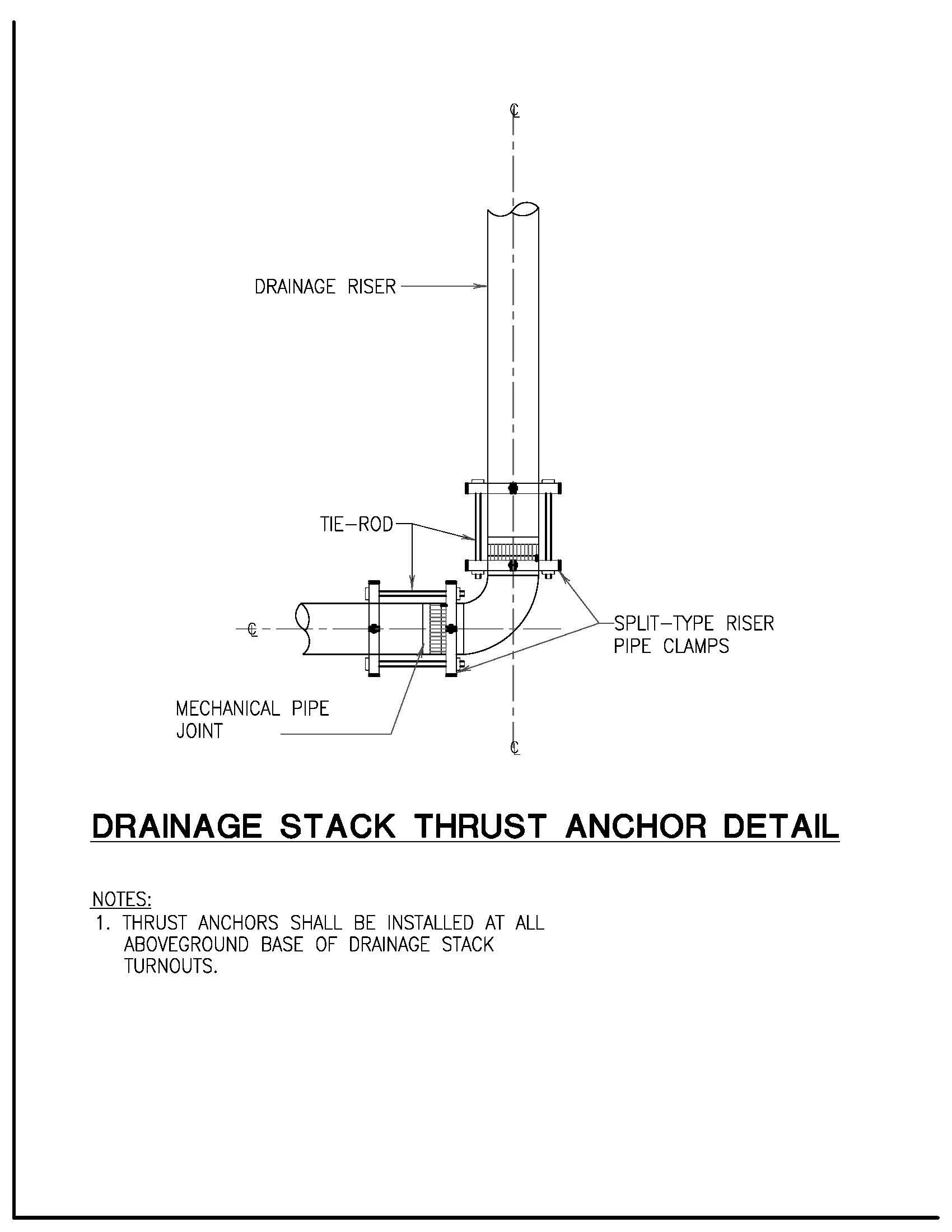
A related concern is the bear on of the hydraulic jump on the piping itself. The mass of water and the rapid alter of velocity from vertical to horizontal crusade this jump. While the pressure associated with this jump is significant, information technology does non destroy the plumbing fixtures at the base of the stack. Rather, the movement of the piping stresses the frictional forces that concord the joint to the pipe, leading to eventual coupling failure. Good design must compensate for the potent thrust that occurs at this alter of direction. Successful methods include increasing the horizontal drain size and/or slope, using thrust blocks, or using restraining joints with threaded rod or similar arrangements that mechanically anchor the fitting to the entering and leaving pipe.
Venting
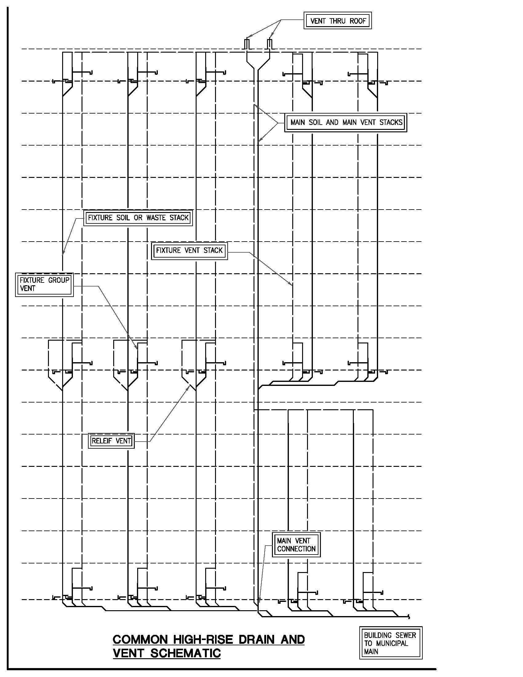
In one case the water is raised and used, information technology is discharged to a drainage system that includes an attendant venting system, which is responsible for the menses of air in the drainage pipe network. Air is disquisitional to the drainage procedure because drainage flow is caused by sloping pipes, and the motive strength is gravity. Absent air, the drainage would range from erratic to nonexistent. When the h2o in a piping flows to a lower area, air must be added to supercede the water, or a negative pressure zone volition occur. If this zone is near a fixture, air will be drawn into the drainage organisation through the fixture trap with an easily identified gulping sound and very slow drain performance. This status will atomic number 82 to poor performance throughout the drainage system and trap seal loss due to siphoning or blowout. The remedy for this condition is venting. At the individual fixture level, this consists of a fixture vent. Equally the number of fixtures increases, venting needs do equally well, evolving into a venting system, with branch, circuit, and loop vents at the appropriate locations. When dealing with high-rise drainage stacks, a vent stack should be attendant, allowing for force per unit area equalization and relief forth the acme and breadth of the organization. Bated from relieving force per unit area in the drainage system, the vent arrangement allows air to circulate in both directions in response to the fluctuating flow in the drainage system. In many high riser vent designs, where stacks need to commencement horizontally on a given floor, a relief vent is required. Although not often highlighted, the building venting system also serves to supplement the vent for the municipal sewer, relieving noxious or even hazardous gases and assuasive the sewer to drain without pressure level limitation.
Vertical Piping
Plumbing engineers must consider the impact of plumbing systems on general construction practices. Nigh experienced engineers and contractors will concur that vertical piping systems are by and large more than constructive than horizontal piping systems in multilevel projects. Vertical piping uses fewer supports, hangers, inserts, etc. and requires less horizontal space in ceiling plenums for sloping to achieve drainage. Altogether, vertical pipe is a pretty skillful bargain; however, it is not without penalty. The penalty of vertical pipe is multiple penetrations through structural slabs. Each of these penetrations must exist sealed or protected to prevent vertical migration of fire and fume (i.due east., turning the tall building into a tall chimney). Non merely is the sealing of penetrations an issue, but the sheer number of penetrations can be equally hard. The location of these multiple penetrations is critical to the integrity of the structure and the function of the fixtures even more than than the aesthetics of the built environment. Higher buildings require more robust structures, further limiting the allowable spaces for penetrations. Other structural practices, such as post-tensioned beams and slabs, which serve to lighten the overall building structure, can limit even further the available locations for slab penetrations. Successful high-rise blueprint requires the entire design team to have extra endeavour to read, understand, and interpret the bear upon of building systems on one another, besides as be open to discuss, coordinate, and adjust each individual system to suit the needs of the building. A well-executed high-ascent design is an integrated and circuitous assembly, and each component should exist treated as a office of that integrated whole.
Burn Protection
One expanse that should not be overlooked in whatsoever loftier-rise design is the burn protection systems. As a minimum, all high-rise buildings should have sprinkler systems on each floor and standpipe systems in each stairwell. These systems have proven themselves throughout the years to significantly save both life and property. The specific type, coverage density, and outlet placement all vary based on the edifice type, height, and location and local fire regime. All high-ascension buildings containing #re protection systems accept large, dedicated fire pumps to provide the flows and pressures required for the individual system. While non e'er tasked with these system designs, plumbing engineers need to know that these systems are an integral part of the building and must account for their presence regarding equipment space, riser locations, and ceiling cavities.
Materials
In the projects touched on in this article, piping systems have been specified and installed using very "standard" pipage and fittings. Sanitary and vent pipage and storm h2o piping within the building are generally hubless cast iron, selected primarily for availability and placidity operation. Underground germ-free and rainwater is hub and spigot cast iron with gasket joints. In some instances, particularly horizontal, large-bore drainage beneath grade, the piping is ductile iron with mechanical-blazon joints. This is a routine installation for this type of piping system, used widely because its suitability to flow and force per unit area, availability, and quiet performance, and largely made of mail service-consumer product, so information technology is very "green" in application. Water systems for these buildings are typically Type L copper. Tubing sizes two inches and smaller are typically assembled using 95-5 solder; for larger bore tubing, nosotros usually exit the contractor the choice to braze or use mechanical joints with roll groove fittings. Medical gas distribution is typically Type L copper with brazed joints as outlined by NFPA. Except for extremely alpine buildings, these materials generally give skilful service over a broad pressure level range and are inside maximum pressure limits by significant amounts. Equally buildings get taller, many water systems tin can exert pressures that exceed the rubber working force per unit area of copper tubing. In some areas, stainless steel light wall pipage (Schedule 10) or standard pipe (Schedule 40) is a reasonable alternative to increment safe working pressures. Both of these materials tin be joined using roll groove mechanical joints.
Circuitous High-Rise Structures
Moving from the very general discussion most basic concepts of design and organisation coordination, one must consider pressure piping in the water supply and distribution system, as well as general drainage and venting approaches. Finally, plumbing engineers must recognize the impact of plumbing installation on the edifice structure. All of these discussions apply, in various degrees, to any type of high-ascension building: office, condominium, hotel. These challenges multiply when plumbing engineers design buildings that are more complex because of function, such as hospitals. Typically, hospitals take a higher density of plumbing fixtures than most other types of buildings, leading to more penetrations to serve them.
Hospitals offer a challenge because they require so many more systems. Aside from the routine rainwater, sanitary bleed and vent, and cold water systems, hospitals oft have other special piping needs, such equally laboratory waste, medical gases, or multiple h2o temperatures to serve patient care or cleaning and sanitizing purposes. Each of these additional systems must be complete and follow the general requirements of the systems already discussed.
Many hospitals have laboratories, and some other types of institutional buildings may have drainage systems to serve chemic- or acrid-using fixtures or equipment. Where this occurs, it is important to ascertain acceptable piping materials, in both suitability to the medium being piped as well every bit acceptability to the local authority. Loftier silicon fe, borosilicate drinking glass, polypropylene, and PVDF are all commonly used. Different materials have different strengths and weaknesses. Iron and glass pipage are well-nigh universally suitable for apply with most acids, bases, and similar chemicals. Both are heavy and crave more than infinite for installation, but they are not easily attacked past flame or generate heavy fumes and smoke. Simple penetration protection is acceptable in most locations. On the other paw, plastic products tin be somewhat troublesome for both chemical drainage systems in general and high-rising buildings in item. They have a narrower list of chemicals that they resist well, and they are more delicate equally well as susceptible to failure by flame exposure. Plastics also may cause smoke-generation problems that must be addressed to maintain life rubber. Resolution of these installations may vary past location and authorisation having jurisdiction. Regardless of the material and approval received, chemical, acid, and laboratory drainage and vent systems must exist carve up from the domestic drain and vent systems used throughout the building.
In one recently completed high-rise laboratory building, biological research labs were on the upper four floor levels. Each of these lab spaces was served by an acid- and chemical-resistant bleed and vent system, separate from the domestic drain and vent systems, that extended to connection at a monitoring station at the junction with the edifice sewer. In this case, glass piping was selected as the proper material, offering the benefits and longevity of that fabric. On the highest level, a bio-safety containment facility was added for critical enquiry in a fully secured environment. Fifty-fifty though this floor used products and materials identical to the adjacent lower floors, the piping circuits were segregated and protected from potential discharge to the environment until passing through a sterilization facility. Fifty-fifty the vents were filtered to preclude uncontrolled belch to the surroundings. This containment facility too housed a small population of research animals, which were accordingly safeguarded and cared for, including muzzle-washing and autoclave equipment to protect against infection. Drainage from this equipment is a high-temperature waste product, which often causes difficulty with leakage when using i of the available plastic products.

Multiple water temperatures required for different operations pb to some other increase in piping and penetrations. This is not only for the supply side, such as cold water distribution, but also for the circulating hot water piping. Usually each water temperature must circulate independently, but occasionally multiple risers or multiple-temperature circulating piping can be combined to render to the heater or mixing valve. Finally, in that location are the medical pipeline gases. Codes require distribution for patient uses to be horizontal, on each floor, with zone valve boxes and expanse alarm panels. These distribution systems must be fed from sources that are usually remote, thus requiring another set of supply risers.
Many of the weather condition already described could apply to any number of projects. The full general discussion well-nigh pressure and control is based on practices used successfully in office building, hotel, and condominium designs throughout the United States. Each of these projects has major similarities and only subtle differences depending largely on construction methods, and less so on decisions of the local authority. These are very basic practices, and variations are currently beingness used in active design projects including condominium, part, hotel, and museum projects. The examples used to illustrate the infirmary conditions are also existent and are actually some of the design limitations encountered on projects that are even so in construction at the fourth dimension of this writing.

An Case
A particular new hospital has a number of additional plumbing design opportunities across those associated with loftier-ascent construction. Beginning, this project is an infill project, constructed betwixt ii wings of an existing high-rise hospital, one of which is as well involved in a vertical expansion and facility upgrade to the ICU floors. A second interesting task was the relocation of several active drainage systems serving the hospital and exiting through this project's site, which included master and secondary storm drainage, sanitary drainage, relocation of the grease waste product drainage from a significant food grooming area, installation of a new passive-type interceptor, relocation of acid-resistant drainage from a major laboratory function, and installation of a new acid neutralization bowl. The new interceptor and neutralization basin and outfalls are located in the private perimeter roadway that surrounds the building. Some other area of coordination with the underground systems is the addition of a new branch from the central utilities on campus, designed and installed as a separate contract by a carve up applied science and contracting team. This included high-pressure steam and condensate, chilled water supply and return, emergency ability duct bank, primary high-voltage power supply, phone, and cobweb optic. All of these modifications were required to be completed before the showtime floor slab was poured.
Fifty-fifty afterward the surreptitious adventures were covered, the building connected to present creative opportunities to the design team. The slab spacing was determined to copy those in the existing hospital, which were very short intervals. This led to an approach that is unremarkably used for hotel-type construction, using multiple vertical risers placed in the toilet chases to serve multiple floors. Of course, this arroyo was required to be modified considering of the irregular stacking of like fixture groups from floor to flooring and the relatively large floor plates (varying between 22,000 and 24,000 square anxiety per floor). Additional complexity was provided past the modern HVAC requirements for medical facilities and the bear on of ceiling plenums, high-density communication and data systems, and high ceiling elevations for more spacious aesthetics on typical patient care floors. Interspersed throughout the building were specialty areas, such as isolation rooms, patient preparation and patient step-down recovery, and ADA-accessible patient rooms. Each of these areas required a unique solution or a variant of those heretofore unique solutions. The ultimate solution for the project was a combined system using big, centrally spaced main waste matter and main vent stacks that immune each smaller fixture riser to extend to the main stacks individually or every bit a building drain. The riser diagram that resulted has a distinctive fan- or castor-shaped outline where all piping funnels together into the main stack. In the final configuration, this building concluded with three main soil, waste, and vent stacks, 2 chief rainwater stacks, one chief water supply riser, and one main medical gas riser.
Information technology'due south Nonetheless, Right
As this word illustrates, mod loftier-rising design is frequently a series of design concepts that must be tested through analysis and coordination, and then adjusted during the coordination period to maximize flexibility and constructability. This exercise is disquisitional for all building trades but particularly so for plumbing systems, for which pipe must be accurately placed or deemed for in the early on construction phases, while the fixture mounting and finishing connections are made much later subsequently the piping systems are concealed. It also highlights the need for designers and engineers to have a familiarity with the piece of work of their peers in other trades. This allows for a certain amount of anticipation betwixt trades, which should exist benign to the overall project.
In summary, I take chop-chop reviewed the process of high-rise plumbing design, particularly focusing on pressure control and on the affect of piping systems on the full general construction of the edifice. Yous can see that although many solutions are routine and similar in application, each approach has trade-offs that must be identified, evaluated, and committed to on each unique project. This understanding supports the notion that proficient engineering is thoughtful and proactive and that good engineers are open up to frank discussion and understanding pertaining to their own trade piece of work, equally well as that of other trades that are involved in the edifice. All high-rise buildings, in design and construction, are significant undertakings for anybody involved. All buildings are unique in form and specific design solutions. It takes a collaborative effort and a determined outlook to reach success in loftier-rise design and construction. Proficient high-ascent plumbing design makes even the tallest of structures more comfy and safer for all building occupants, and good technology and pattern practices and experiences plow the most daunting loftier-ascent design into a matter of scale.
In the final analysis, I believe the answer to the question is "yeah." It is nonetheless—all high-rising buildings are such complex organisms that they require close scrutiny and evaluation to maximize the project'due south potential for the owner and to create a design that is robust plenty to serve the needs of the edifice for years to come, and notwithstanding provide for affordable structure.
"High-Rise Plumbing Design: It's all the same, right?" was published in the May/June 2007 edition of the Plumbing Systems & Design Mag past the American Society of Plumbing Engineers, Inc.
Writer: Dennis Thousand. Connelly, CPD
- Bio
- Latest Posts

With 34 years of feel, Dennis is proficient in plumbing design for commercial and institutional facilities, including campuses for bookish, governmental and corporate clients. He has been published in the areas of pure water system pattern and high-ascension plumbing. He has been responsible for plumbing pattern in more than 500 projects roofing more than 67,500,000 square feet of facilities. Email Dennis
Source: https://www.newcomb-boyd.com/publications-presentations-seminar-notes/high-rise-plumbing-design-its-all-the-same-right/
Post a Comment for "High Rise Salon Mechanical Plan Drawing Chicago Hydraulic"